
The Ultimate Guide to Pole Mounted Transformers
A pole-mounted transformer changes distribution-system voltage to the voltage required by nearby customers. Choosing one involves more than matching a kVA number: the primary connection, secondary service, protection, losses, mounting arrangement, and utility specification must all work together.
This guide explains the equipment from the inside out, then walks through sizing, voltage notation, transformer banks, testing, maintenance, and purchasing. North American examples are identified where used; they are not universal specifications for other countries.
How to use this guide: Start with Sections 1–7 for fundamentals, Sections 8–11 for calculations and connections, Sections 14–22 for engineering requirements, and Sections 30–32 for replacement and procurement. Numerical examples are illustrative calculations, not measurements from a real project.
1. What Is a Pole Mounted Transformer?
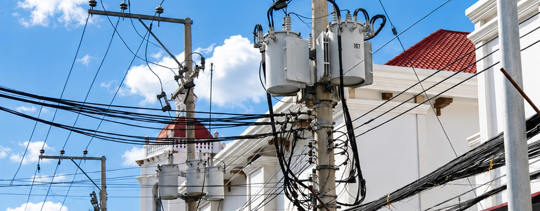
A pole-mounted transformer is a distribution transformer installed above ground on a utility pole or an engineered pole structure. It typically steps primary distribution voltage down to the service voltage required by nearby customers. The term describes the mounting arrangement; the transformer may serve single-phase or three-phase loads, depending on its design and connections.
What does it do, and where does it sit in the network?
A pole-mounted transformer normally provides a local voltage-conversion stage between a primary distribution feeder and customer service conductors. The equipment is installed above ground, close enough to the load to make the secondary distribution practical.
“Pole-mounted” describes the installation arrangement. “Distribution transformer” describes its role. Distribution transformers also include pad-mounted and other configurations; the terms are therefore related but not interchangeable. Hitachi Energy identifies residential, commercial, light-industrial, and commercial-lighting applications for its pole-mounted product range.
What other names are used?
Readers may encounter pole transformer,telephone pole transformer,pole-top transformer,pole type transformer, overhead distribution transformer, conventional/CSP pole mounted transformer,and the informal term pole pig. In procurement, use “pole-mounted distribution transformer” and specify phase, ratings, and protection explicitly. A nickname cannot identify the required electrical configuration.
2. How Does a Pole Mounted Transformer Work?
A pole-mounted transformer transfers electrical energy between windings through electromagnetic induction. Alternating current in the primary winding creates changing magnetic flux in the core, which induces voltage in the secondary winding. The winding turns ratio determines the approximate voltage ratio. In normal step-down service, it supplies lower-voltage AC at the same frequency as the source.
How does electromagnetic induction change voltage?
Alternating current in the primary winding produces changing magnetic flux in the core. That flux links the secondary winding and induces an alternating voltage. For an ideal transformer:
Vₚ / Vₛ = Nₚ / Nₛ
Here, V is winding voltage and N is winding turns. A step-down transformer has a lower secondary voltage than primary voltage. Ignoring losses, current changes in the opposite ratio, so power is approximately conserved. A transformer does not generate extra energy.
Does it convert AC to DC or change frequency?
An ordinary transformer supplies AC at the same frequency as its source. Rectifiers or other power electronics are needed for AC-to-DC conversion.
For an illustrative 7,200 V to 240 V transformer, the ideal turns ratio is 30:1. A center-tapped secondary can provide 120 V across either half and 240 V across the full winding. The nameplate connection diagram determines the permitted arrangement; the example is not a universal pole-transformer voltage specification.
3. What Are the Main Parts of a Pole Mounted Transformer?
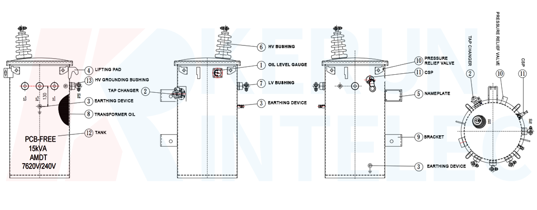
The main parts of a liquid-filled pole-mounted transformer are its magnetic core, primary and secondary windings, insulation system, insulating fluid, tank, and bushings. External fittings provide electrical connections, grounding, lifting, mounting, and identification. Tap selectors, pressure-relief devices, and integrated protection may also be included, depending on the specified design.
What is inside the tank?
The core carries magnetic flux; primary and secondary windings transfer energy through that flux. Solid insulation and insulating fluid provide electrical separation. The fluid also carries heat toward the tank and, where fitted, cooling surfaces.
Which external components should buyers recognize?
| Component | Function |
|---|---|
| Tank and cover | Enclose the active assembly and fluid |
| High- and low-voltage bushings | Provide insulated electrical passages through the enclosure |
| Tap changer, if fitted | Selects an available winding ratio |
| Grounding terminal | Provides a designated bonding connection |
| Pressure-relief device, if fitted | Relieves pressure within its rated capability |
| Lifting lugs and mounting brackets | Provide designated handling and support points |
| Nameplate | Identifies ratings, connections, and the individual unit |
4. What Equipment Is Installed Around a Pole Mounted Transformer?
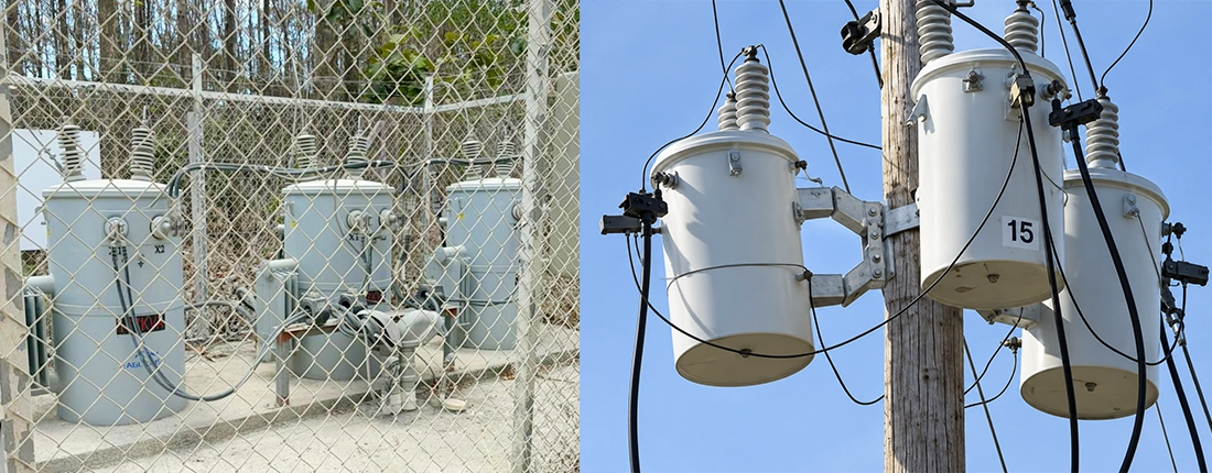
Equipment around a pole-mounted transformer commonly includes fuse cutouts, surge arresters, primary and secondary conductors, insulators, grounding connections, and support hardware. Wildlife guards may protect exposed interfaces. Together, these components connect, support, and protect the installation, but they are not necessarily included in the transformer supplier’s scope.
Is everything on the pole part of the transformer?
No. A pole installation can include a fuse cutout, surge arresters, conductors, insulators, mounting hardware, grounding connections, and wildlife guards. Some devices may be attached to the transformer; others belong to the surrounding distribution installation.
Why should the supply boundary be explicit?
An RFQ should distinguish the transformer supply from the complete pole-top installation. Ask who supplies the cutouts, arresters, brackets, connectors, and installation drawings. Otherwise, apparently comparable quotations may cover different equipment.
Ausgrid’s construction specification, for example, addresses protective devices and pole-substation construction as an installation system. Its requirements apply to its network and should not be copied indiscriminately into another utility’s project.
5. What Types of Pole Mounted Transformers Are Available?
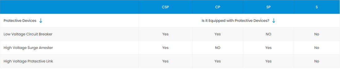
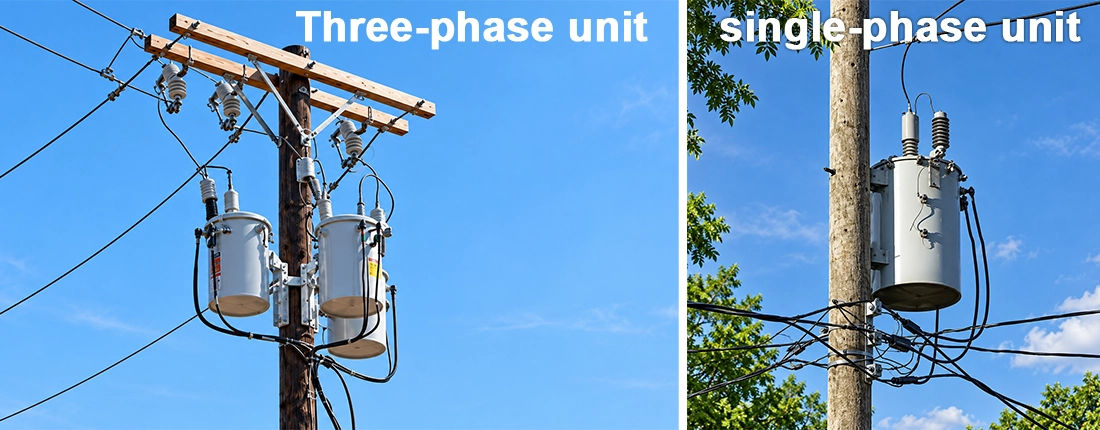
Pole-mounted transformers can be classified by phase arrangement and protection configuration. Electrical options include single-phase units, three-phase units, and banks of separate single-phase transformers. Protection options include conventional and completely self-protected (CSP) designs. These categories overlap: a single-phase transformer, for example, may be conventional or CSP, with a protection package specific to the supplied model.
Single-phase, three-phase, or a transformer bank?
A single-phase unit serves a suitable single-phase load. A three-phase unit contains the windings needed for three-phase service in one assembly. A bank connects separate single-phase transformers to serve a three-phase system. The available primary supply and required secondary service determine which arrangement is feasible.
What is a conventional transformer?
A conventional unit is supplied without the complete integrated protective package associated with a self-protected design. The installation provides the required protection through specified external and/or optional devices. Eaton offers conventional overhead units in a stated product range; that range should not be mistaken for every manufacturer’s capability.
What does CSP mean?
CSP means **completely self-protected**. Eaton describes configurations using directly connected primary arresters with a MagneX interrupter, or a secondary breaker with internal primary-voltage fuses. Thus, “CSP” does not establish one identical bill of materials across all ratings and suppliers.
| Selection issue | Conventional configuration | CSP configuration |
|---|---|---|
| Protection specification | Define the external and optional protection | Identify the exact integrated devices |
| Maintenance planning | Coordinate separate equipment and spares | Confirm access and replacement procedures for the supplied package |
| Purchasing check | List excluded pole-top accessories | Obtain protection ratings and coordination data |
Neither label is universally better. Ask which configuration the utility approves and how it fits the operating and maintenance plan.
6. What Ratings and Specifications Define a Pole Mounted Transformer?
A pole-mounted transformer is defined by its kVA rating, primary and secondary voltages, phase, frequency, insulation levels, impedance, tap arrangements, temperature rise, and cooling designation. A complete specification also identifies construction materials, fluid, protection, environmental conditions, and mounting interfaces. The correct combination must satisfy both the electrical system and the utility’s installation requirements.
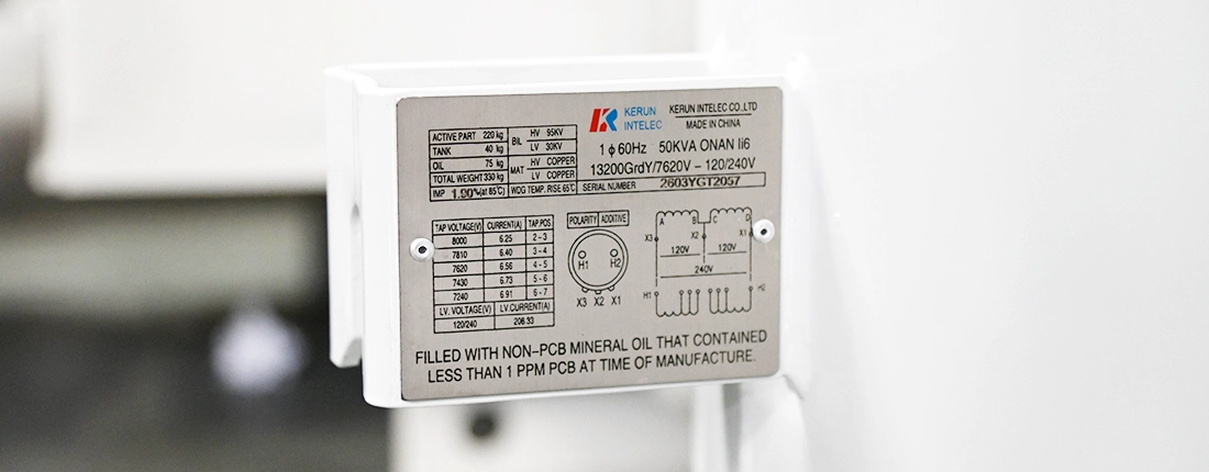
What do the main nameplate ratings mean?
| Rating | Meaning and purchasing question |
|---|---|
| kVA | Apparent-power rating; what load and duty must it support? |
| Primary voltage | Required voltage across the primary winding; what is the actual connection? |
| Secondary voltage | Required output and terminal arrangement |
| Phase | Single-phase or three-phase service |
| Frequency | Design frequency, commonly 50 or 60 Hz |
| BIL | Basic lightning impulse insulation level; a withstand rating, not operating voltage |
| Percent impedance | Series impedance on the transformer’s rating base; relevant to fault current and regulation |
| Temperature rise | Permitted rise under specified conditions, not an ambient-temperature rating |
| Cooling designation | Fluid and external cooling media and their circulation methods |
These are distinct design variables; meeting one does not imply that the others are suitable.
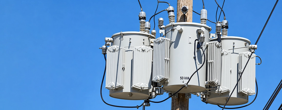
What does ONAN cooling mean?
ONAN describes oil natural circulation and air natural cooling: heat moves through the fluid and into the surrounding air without a forced-cooling system in that designation. For other fluids, confirm the actual cooling designation rather than automatically labeling every liquid-filled transformer ONAN.
What are taps, and can they be changed while energized?
Taps provide specified winding-ratio choices. A de-energized tap changer must only be operated under the manufacturer’s approved de-energization procedure. It is not an automatic voltage regulator or an on-load tap changer.
What environmental information belongs in the specification?
State ambient-temperature limits, altitude, coastal exposure, pollution, and unusual mechanical or climatic conditions. Ask the supplier to confirm the resulting rating and construction. Do not apply one generic altitude or ambient derating percentage to every design.
7. What Are the Common kVA Sizes of Pole Mounted Transformers?
Examples of single-phase pole-transformer ratings include 5, 10, 15, 25, 37.5, 50, 75, 100, 167 and 333kVA documented conventional overhead range. Three-phase offerings and utility-approved ratings differ by manufacturer and network. There is no single worldwide rating series or maximum capacity that applies to every pole-mounted installation.
| 10kVA–500kVA Single Phase Pole Mounted Transformer | ||||||
|---|---|---|---|---|---|---|
| Rated Capacity (kVA) |
High Voltage (V) | Low Voltage (V) | Connection Symbol | Standard | Short-circuit Impedance (%) | Efficiency (%) |
| 10 | 4160 7200 12000 12470 13200 13800 19920 24940 34500 |
110 220 230 400 480 |
II0, II6 | IEEE/ANSI/ DOE |
1.8–4% | 98.70 |
| 15 | 98.82 | |||||
| 25 | 98.95 | |||||
| 37.5 | 99.05 | |||||
| 50 | 99.11 | |||||
| 75 | 99.19 | |||||
| 100 | 99.25 | |||||
| 167 | 99.33 | |||||
| 250 | 99.39 | |||||
| 333 | 99.43 | |||||
| 500 | 99.49 | |||||
Kerun manufactures single-phase pole-mounted distribution transformers from 5 kVA to 500 kVA, with configurable primary and secondary voltages. Designs can be manufactured to applicable IEC, IEEE/ANSI and customer-specified requirements, with controlled processes for loss performance, insulation, sealing and dimensional consistency.
Are three-phase ratings and maximum sizes universal?
No. IEEE C57.12.20-2023 covers specified overhead transformers through 500 kVA. These are three different kinds of scope: manufacturer offering, utility practice, and standard coverage.
Buyer takeaway:Neither 167 kVA nor 500 kVA is a universal physical limit. A proposed transformer must fit an approved structural arrangement and the supplier’s actual design range.
How much secondary current does a stated kVA represent?
For a single-phase 240 V output, calculated rated current is kVA × 1,000 / 240. The table applies to the full 240 V winding; it does not authorize drawing the entire kVA from one 120 V half-winding.
| Single-phase rating | Calculated current at 240 V |
|---|---|
| 25 kVA | 104.2 A |
| 50 kVA | 208.3 A |
| 75 kVA | 312.5 A |
| 100 kVA | 416.7 A |
| 167 kVA | 695.8 A |
These are arithmetic conversions, not recommended service-breaker sizes or permitted overload ratings.
8. How Do You Size a Pole Mounted Transformer?
Size a pole-mounted transformer from the expected coincident load demand, expressed in kVA, then evaluate starting duty, phase balance, harmonics, environmental conditions, and planned growth. Select an available, utility-approved rating that meets the resulting thermal and voltage-performance requirements. Adding all connected nameplate loads or applying a fixed growth percentage alone does not establish the correct size.
How do you calculate kVA from voltage and current?
For a single-phase circuit using RMS voltage and current:
S (kVA) = V × I / 1,000
For a balanced three-phase circuit:
S (kVA) = √3 × V_LL × I_L / 1,000
V_LL is line-to-line voltage and I_L is line current. For an unbalanced system, assess each phase rather than relying only on the balanced formula. If real power and power factor are known, kVA = kW / PF.
How do connected load, demand, and diversity differ?
Connected load is the total installed load. Maximum demand represents the greatest coincident demand over a defined interval. Using conventional engineering definitions:
- Demand factor = maximum coincident demand / connected load.
- Diversity factor = sum of individual maximum demands / group coincident maximum demand.
- Coincidence factor = 1 / diversity factor, when based on the same loads and period.
Under these definitions, diversity factor is at least 1. A multiplier such as 0.8 is not this definition of diversity factor. Always identify the formula being used.
How much growth margin should you allow?
Use a documented load forecast, not an automatic 20% or 25% rule. Check motor starting, voltage drop, harmonic loading, phase imbalance, expected load duration, and future electrification. A transformer that carries the running kVA can still produce unacceptable voltage dip when a motor starts.
What does a preliminary sizing calculation look like?
The following examples use invented inputs solely to demonstrate arithmetic. Candidate sizes require a separate engineering and utility review.
Residential example
Assume an assessed diversified peak of 32 kVA, with a separately justified 20% planning allowance:
32 × 1.20 = 38.4 kVA.
If the approved series includes 37.5 and 50 kVA, 50 kVA is the next candidate rating. This does not establish how many houses any real 50 kVA transformer can supply.
Farm and irrigation example
Assume a balanced three-phase pump load at 400 V and 50 A:
√3 × 400 × 50 / 1,000 = 34.64 kVA.
Add 8 kVA of simultaneous auxiliary demand as a conservative scalar allowance: 42.64 kVA. With an assumed 20% planning allowance, the result is 51.17 kVA. Evaluate the next utility-approved rating above that value, then check starting duty and voltage dip. Motor shaft kW cannot be used as electrical-input kW without accounting for efficiency.
Small commercial example
Assume electrical demand of 72 kW at PF 0.90:
72 / 0.90 = 80 kVA.
An assumed 15% growth allowance gives 92 kVA. A 100 kVA arrangement is a candidate if available and approved. Three-phase bank selection also requires suitable per-unit ratings and acceptable load balance.
9. How Many Houses Can One Pole Transformer Supply?
One pole-mounted transformer may supply an individual property or several homes, but its kVA rating alone cannot determine the number. The result depends on coincident household demand, heating and cooling loads, EV charging, climate, and the utility’s loading criteria. A 25, 50, or 75 kVA transformer therefore has no universal house-count rating.
Can the number of homes be determined from kVA alone?
There is no universal number of homes per transformer.A 25, 50, or 75 kVA unit must be evaluated against coincident demand, local climate, heating and cooling loads, EV charging, and the utility’s loading criteria.
Dividing kVA by an assumed “average household load” mixes different quantities unless that load is a suitable coincident design demand. A home’s service-breaker rating also does not represent its continuous demand.
How can EV charging change the result?
Several vehicles charging together can create a local peak even if total regional generation is adequate. DOE’s Alternative Fuels Data Center identifies concentrated coincident charging as a potential strain on nearby distribution equipment.
For an arithmetic illustration, three simultaneous 7.2 kW chargers at approximately unity power factor add about 21.6 kVA. Actual charging power, control settings, and other loads must be checked. Managed charging can change the load profile, but its benefit must be demonstrated rather than assumed.
10. What Is the Difference Between Line-to-Line and Line-to-Neutral Voltage?
Line-to-line voltage is measured between two phase conductors; line-to-neutral voltage is measured between a phase conductor and neutral. In a balanced three-phase wye system, line-to-line voltage equals √3 times line-to-neutral voltage. A center-tapped single-phase 120/240 V system has a different relationship. Identifying the actual connection is essential when specifying transformer winding voltage.
When does the √3 relationship apply?
Line-to-line voltage is measured between phases. Line-to-neutral voltage is measured between a phase and neutral. For a balanced three-phase wye system:
V_LL = √3 × V_LN
For a center-tapped single-phase 120/240 V secondary, the full winding is 240 V and each half is 120 V. That is a 2:1 relationship, not √3.
What does 12.47Y/7.2 kV mean?
It identifies a wye-system relationship of approximately 12.47 kV line-to-line and 7.2 kV line-to-neutral. A single-phase transformer connected phase-to-neutral sees the latter voltage. A phase-to-phase primary connection sees line-to-line voltage and requires a winding rated accordingly.
Similarly, a balanced 13.8 kV line-to-line wye system has approximately 7.97 kV line-to-neutral. Merely writing “13.8 kV primary system” leaves a crucial purchasing question unresolved. Eaton’s fundamentals page illustrates the distinction between system-voltage designations and transformer voltage ratings.
What should the RFQ say?
Provide the system voltage, grounding arrangement, intended primary connection, required winding voltage, insulation level, and utility connection drawing. Ask the supplier to confirm these explicitly before manufacturing.
11. How Are Pole-Mounted Transformer Banks Connected?
Pole-mounted transformer banks connect separate single-phase units to provide the required three-phase service. Arrangements include wye-wye, delta-wye, delta-delta, and open delta. The selected connection determines voltage relationships, neutral availability, phase displacement, and usable bank capacity. Ratios, polarity, impedance, and grounding must be compatible with the intended network and load.
What are the common bank arrangements?
| Arrangement | Essential distinction |
|---|---|
| Wye-wye | Both sides use star connections; neutral and grounding behavior require analysis |
| Delta-wye | Delta primary and star secondary; specify neutral service and phase displacement |
| Delta-delta | Delta connections on both sides; ordinary delta has no neutral unless specially configured |
| Open delta | Two suitably connected single-phase transformers can supply three-phase power at reduced bank capacity |
A bank is not simply three interchangeable cans. Ratios, polarity, impedance, phase sequence, and connection details must suit the intended service.
What is the correct open-delta capacity calculation?
For two equal units of rating S_unit, supplying a balanced three-phase load under the usual idealized rating calculation:
S_open-delta = √3 × S_unit.
For two 50 kVA units, that is 86.60 kVA. Compared with a closed-delta bank of three 50 kVA units, 86.60 / 150 = 57.7%. Compared with the sum of the two installed nameplates, 86.60 / 100 = 86.6%.
The denominator matters. Applying 57.7% to the two installed nameplates is incorrect. Schneider Electric documents the 57.7% relationship to the original three-transformer bank. Mixed single-phase and three-phase loading requires a more detailed assessment.
12. Where Are Pole-Mounted Transformers Used?
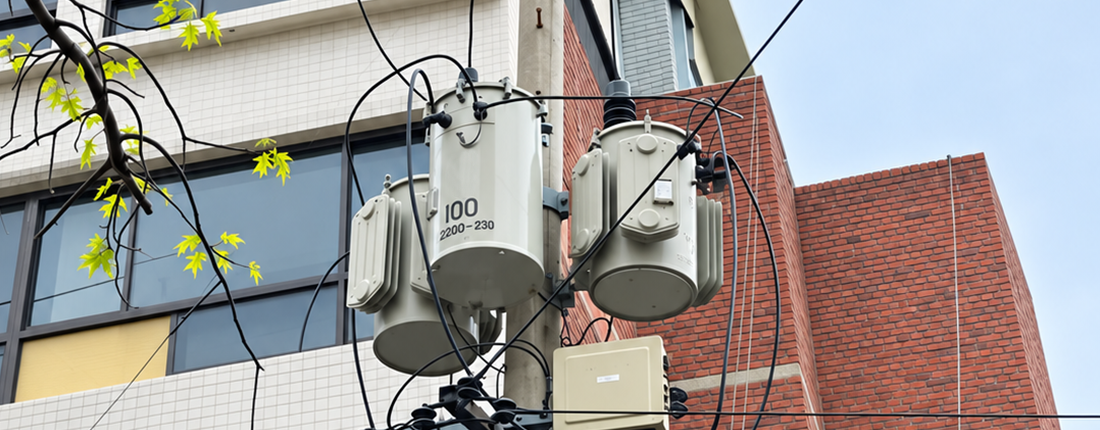
Pole-mounted transformers serve local loads where an overhead distribution arrangement is suitable. Applications include residential neighborhoods, rural communities, farms, commercial premises, lighting, and appropriate light-industrial facilities. The required capacity, voltage, phase arrangement, site access, and utility rules determine suitability; the application label alone does not establish which transformer should be selected.
Which applications suit overhead distribution?
Examples include residential service, rural electrification, farms, small commercial premises, lighting, and suitable light-industrial loads. The installation is most useful where the distribution layout, access, and structural conditions support it.
Can they serve pumps, telecom facilities, solar, or batteries?
Those applications should be assessed by electrical requirements rather than their industry label. A pump introduces starting-duty questions; remote equipment may have unusual access or reliability needs; solar and batteries introduce export and interconnection questions.
For a renewable-energy project, ask the utility to assess import and export operating cases, voltage behavior, protection, and approved equipment. An existing transformer’s kVA nameplate alone is not authorization to connect generation.
13. Pole-Mounted vs Pad Mounted Transformer: What Is the Difference?
A pole-mounted transformer is supported above ground by a pole or pole structure, while a pad-mounted transformer is installed at ground level on a foundation with a protective enclosure. Pole-mounted equipment commonly serves overhead distribution; pad-mounted equipment commonly connects to underground cables. The choice affects space, access, civil work, clearances, and the complete installation cost.
How does the mounting arrangement affect the project?
| Issue | Pole-mounted | Pad-mounted |
|---|---|---|
| Support | Pole or engineered pole structure | Ground-level foundation or pad |
| Connections | Commonly associated with overhead primary distribution | Commonly associated with underground cables |
| Space planning | Pole location, clearances, structural capacity, elevated access | Equipment footprint, working clearances, cable routes, vehicle protection |
| Service access | Elevated work and suitable lifting access | Ground-level access under controlled procedures |
| Project costing | Include pole work, hardware, access, and conductors | Include foundation, excavation, ducts, and cable termination |
These are planning comparisons, not an absolute rule linking every transformer to one feeder type. Eaton’s materials distinguish compartmental pad-mounted construction and connection arrangements from overhead equipment.
Is one always cheaper or safer?
No universal installed-price or safety ranking follows from the mounting type. Compare actual site designs, access controls, clearances, exposure, and maintenance arrangements. A ground-level unit requires suitable enclosure security; an elevated unit requires suitable pole support and access management.
14. How Are Pole Mounted Transformers Protected?
Pole-mounted transformers use coordinated protection to address different hazards. Fuses or breakers interrupt specified overcurrents, surge arresters limit transient overvoltages, and grounding and bonding provide required equipment and system connections. Pressure-relief devices and wildlife guards address additional risks. The required combination depends on the transformer design, available fault current, and utility protection scheme.
What problems do different devices address?
| Device or feature | Intended role |
|---|---|
| Fuse cutout or specified primary fuse | Interrupts overcurrent within its selected operating characteristics |
| Surge arrester | Limits transient overvoltage |
| Current-limiting fuse | Limits fault-current let-through within its applicable operating range |
| CSP secondary breaker, where supplied | Provides specified secondary overload and fault protection |
| Bonding and grounding | Establishes required equipment and system connections |
| Pressure relief | Provides a rated pressure-release function |
| Wildlife guards | Reduce animal contact at exposed interfaces |
purchasing one option does not establish a complete coordinated protection scheme.
Why is coordination necessary?
Ask the protection engineer to verify normal loading, transformer energization inrush, through-fault duty, available fault current, and upstream/downstream operation. A fuse cannot be selected by transformer kVA alone. Transformer inrush is a separate transient from the customer’s motor-starting current.
15. How Is a Pole Mounted Transformer Installed?
A pole-mounted transformer is installed by qualified, authorized personnel using an approved electrical and structural design. The work includes checking the equipment and support structure, planning lifting and mounting, completing specified connections and protection, and verifying the installation before energization. Clearances and operating procedures must follow the applicable utility requirements and manufacturer’s instructions.
Who should perform the work?
Installation, switching, and commissioning belong to qualified, authorized personnel. Eaton’s instructions explicitly require equipment familiarity and training in electrical operating and protective procedures. [S13]
What must be resolved before installation?
The project review should establish an approved arrangement, verified equipment identity, a structural assessment, suitable access and lifting plans, clearances, grounding design, and coordinated protection. Pole condition, transformer mass, eccentric loading, wind, and conductor forces all matter to the support assessment.
Ausgrid’s NS122 links construction to approved drawings and safety rules. This illustrates why a generic mounting-height figure from a blog is not a substitute for the applicable local design.
What must be checked before energization?
Confirm that the installed equipment matches the approved ratings and connections and that the responsible personnel have completed their inspection, test, and operating-clearance requirements. This section is a project overview; it does not provide a field switching or wiring procedure.
16. How Are Pole Mounted Transformers Tested and Commissioned?
Factory testing verifies specified electrical and insulation performance through tests such as ratio, polarity, winding resistance, losses, impedance, and dielectric withstand. Commissioning then checks that the delivered equipment and completed installation suit the approved system. The applicable standards and purchase specification determine the required routine, design, and additional tests and their acceptance criteria.
What does each test establish?
| Test family | Purpose |
|---|---|
| Ratio, polarity, and phase relationship | Verify winding ratio and connection relationship |
| Winding resistance | Check winding resistance and support loss/temperature evaluations |
| No-load loss and excitation | Measure energized, unloaded behavior |
| Load loss and impedance | Measure load-related losses and series impedance |
| Dielectric testing | Verify specified insulation withstand |
| Temperature-rise testing | Demonstrate the thermal performance of a design under specified conditions |
IEEE C57.12.90 addresses test methods for liquid-immersed transformers. The applicable requirements and purchase specification determine which tests are routine, design, or specially requested; do not assume every full design test is repeated on every unit.
What documentation should a buyer request?
Ask for serial-number-linked reports, approved drawings, nameplate and connection details, guaranteed losses, acceptance criteria, and a record of agreed deviations. Clarify any witness-test or additional-report requirements before ordering.
Factory testing verifies the manufactured equipment. Commissioning also checks whether the delivered unit and completed installation match the intended system. One does not replace the other.
17. What Standards Apply to Pole-Mounted Transformers?
Applicable standards depend on the destination, transformer design, and utility specification. IEEE-based projects commonly reference C57.12.20 for overhead-transformer requirements, C57.12.00 for general requirements, and C57.12.90 for test methods. IEC-based projects use the relevant parts of IEC 60076. Enclosure requirements and network-specific specifications also need to be identified, with applicable editions stated in the purchase documents.
Which documents address which requirements?
| Reference | Relevant scope |
|---|---|
| IEEE C57.12.20-2023 | Specified characteristics of single- and three-phase, 60 Hz, liquid-immersed, self-cooled overhead distribution transformers through 500 kVA, within its voltage limits |
| IEEE C57.12.00 | General requirements for liquid-immersed distribution, power, and regulating transformers |
| IEEE C57.12.90 | Test methods for liquid-immersed distribution, power, and regulating transformers |
| IEEE C57.12.30-2020 | Pole-mounted enclosure coating integrity for coastal environments |
| IEEE C57.12.31-2020 | Carbon-steel pole-mounted enclosure coating integrity outside coastal or other severe environments |
| IEC 60076-1 and relevant companion parts | General transformer requirements and the applicable subject-specific requirements |
| Utility and project specifications | Network-specific ratings, interfaces, approved construction, and acceptance requirements |
Does meeting IEEE or IEC automatically mean utility approval?
No. A transformer can meet a general standard yet have the wrong bracket pattern, bushing arrangement, connection, protection package, or documentation for a particular utility.
Specify document numbers, applicable editions, and precedence for resolving conflicts. Utility specifications supplement applicable law and project requirements; they do not automatically override them. Public standard summaries identify scope, but detailed compliance requires the actual applicable standard text.
18. How Efficient Are Pole Mounted Transformers?
Pole-mounted transformer efficiency is the ratio of delivered real power to input real power. It depends on no-load losses, load losses, loading level, power factor, and operating conditions. A single efficiency percentage is meaningful only with its stated test conditions. For purchasing, compare guaranteed losses and expected energy consumption over the actual load profile.
What causes transformer losses?
No-load losses arise mainly in the energized core. Load losses include winding resistance losses and additional load-related effects. A useful simplified model at approximately fixed voltage, frequency, and reference temperature is:
P_loss ≈ P₀ + x² × P_load,rated,
where x is per-unit load. The model explains why reducing core loss is valuable for an energized transformer that spends much of its time lightly loaded. Actual calculations must account for temperature and the load profile.
How do you calculate efficiency?
Efficiency = output real power / input real power × 100%.
For an illustrative 50 kVA unit at 50% load and PF 0.90, output real power is 22.5 kW. If assumed no-load loss is 80 W and full-load load loss is **500 W**, estimated loss is 205 W:
22.5 / (22.5 + 0.205) × 100 = 99.10%.
These assumed losses are not a product specification, a test result, or proof of regulatory compliance.
Can a higher purchase price produce a lower lifetime cost?
Compare purchase cost with expected loss energy, maintenance, and replacement costs over a stated economic period. For annual loss energy, use the time integral of squared loading; squaring the annual average load can understate losses. A 25-year financial analysis period is an assumption, not a guaranteed service life.
19. What Are the U.S. DOE Efficiency Requirements?
U.S. DOE efficiency requirements apply to transformers that fall within the regulatory definition of covered distribution equipment, rather than to every pole-mounted unit. The applicable minimum efficiency depends on the equipment category and rating. DOE’s reviewed guidance distinguishes the 2024 rule’s effective date from the amended standards’ April 23, 2029 compliance date.
Regulatory source checked: September 22, 2026.
Do the rules apply to every pole-mounted transformer?
No. Coverage depends on the regulatory definition and exclusions, not merely the mounting arrangement. DOE’s summary describes covered liquid-immersed distribution transformers as 60 Hz units within specified voltage and capacity limits, including a 10–2,500 kVA capacity range. Check the exact product category.
What is the difference between the 2024 and 2029 dates?
DOE’s current program page states that the amended rule became effective July 8, 2024, and that compliance with its amended standards is required on and after April 23, 2029. Those are different milestones.
DOE also published a **June 15, 2026 request for information** concerning the standards’ effects on manufacturing, supply chains, and related issues. An information request is not itself a replacement final standard; the accompanying DOE announcement still identifies the 2029 compliance timeline.
What should U.S. buyers confirm?
Request the applicable equipment class, required efficiency level, test basis, and compliance documentation for the relevant transaction and manufacturing/import timing. The DOE final-rule material expresses requirements as efficiency levels; it should not be summarized as an unconditional requirement that every transformer use one core material.
Recheck the current rule and any amendments before contracting. An old catalog statement of “DOE compliant” does not establish compliance with every future requirement.
20. Copper vs Aluminum Transformer Windings: What Is the Difference?
Copper and aluminum windings differ in conductivity, density, and the conductor dimensions needed to achieve a given resistance. Copper’s higher conductivity does not, by itself, establish better whole-transformer efficiency or reliability. Buyers should compare complete designs against the same loss guarantees, temperature-rise limits, mechanical requirements, and utility specification rather than judge performance by winding material alone.
Is copper automatically the better choice?
Copper and aluminum are both used as transformer conductors. Copper has higher electrical conductivity; aluminum has lower density. With equal conductor length and temperature, matching resistance requires a larger aluminum cross-section. Whole-transformer performance still depends on the complete design.
Schneider Electric’s published material cautions against assuming that copper alone guarantees superior efficiency, reliability, or short-circuit strength.
What should buyers compare?
Ask each bidder to guarantee losses, temperature rise, impedance, and relevant mechanical performance. Then compare dimensions, mass, terminals, utility acceptance, and total cost on the same basis.
A copper requirement can be a legitimate project condition, but it should be stated explicitly. A supplier should not substitute aluminum without approval, and a buyer should not reject an otherwise compliant aluminum design solely because of an unsupported material-quality claim.
21. GOES vs Amorphous Core: What Is the Difference?
GOES is grain-oriented electrical steel; amorphous transformer cores use a metal alloy with a different material structure and magnetic-loss behavior. Amorphous-core designs can reduce no-load losses compared with conventional silicon-steel designs, but the benefit varies by product. Selection should consider guaranteed losses, loading profile, dimensions, cost, and applicable project requirements.
How do the materials differ?
GOES means grain-oriented electrical steel. Amorphous metal has a different material structure and magnetic-loss behavior. Eaton offers both grain-oriented and amorphous steel options in its reviewed overhead range.
Amorphous-core designs can reduce no-load losses compared with conventional silicon-steel designs. The benefit must be established for the actual products being compared, not by promising one fixed percentage for every transformer. Hitachi’s published example is specific to its stated design and comparison.
Should buyers specify material or guaranteed losses?
Where utility rules permit, a performance-based RFQ can request maximum no-load and load losses, efficiency test conditions, dimensions, and sound requirements, then let suppliers propose a compliant design.
If the project mandates a core material, retain that requirement. Otherwise, evaluate the loss guarantees and economic assumptions rather than treating the material name as a complete efficiency specification.
22. What Insulating Fluids Are Used?
Pole-mounted transformers can use mineral oil or suitable ester-based insulating fluids. The fluid provides electrical insulation and carries heat away from the active assembly. Fluid selection affects fire performance, environmental characteristics, handling, and design compatibility. Use the specified product’s data and utility approval requirements; changing fluid does not automatically increase the transformer’s permitted loading.
How do mineral oil and natural ester differ?
Mineral oil and ester fluids are available in commercial pole-mounted products.Natural-ester products can offer higher fire points and favorable biodegradation properties, but values must come from the actual fluid’s data sheet.
Cargill lists typical FR3 values of **320–330°C flash point** and **350–360°C fire point** under the stated open-cup method. Its technical page also lists biodegradation and other test results. These are product-specific values, not universal numbers for all ester fluids.
Does less-flammable mean fireproof?
No. A fluid’s fire classification does not remove electrical faults, hot surfaces, pressure hazards, or the need for an approved installation. Likewise, biodegradability does not mean a spill can be ignored.
Can fluid be changed without other checks?
Treat fluid selection or retrofilling as a compatibility decision. Confirm utility acceptance, materials, thermal rating, cold-temperature behavior, handling, and the manufacturer’s approval. A different fluid does not automatically authorize a higher kVA rating. Cargill provides a separate storage and handling guide for FR3.
23. How Much Does a Pole Mounted Transformer Cost?
The cost of a pole-mounted transformer depends on its electrical ratings, loss guarantees, construction, protection package, testing requirements, quantity, and delivery terms. Installed cost also includes site work, supporting structures, conductors, labor, and commissioning. A useful price comparison therefore requires matching specifications and supply boundaries; kVA alone is insufficient to establish a reliable price.
Why is there no universal price?
A defensible price requires a defined specification, quantity, date, destination, and commercial scope. A bare transformer price cannot be compared directly with a delivered or installed project price.
The sources reviewed here do not establish a reliable current market-price range covering all pole-mounted transformers. Rather than present an unsupported dollar figure, use a quotation comparison that controls the variables below.
Why can two 50 kVA quotations differ substantially?
| Comparison item | What to make equivalent |
|---|---|
| Electrical configuration | Phase, voltages, primary connection, BIL, taps, impedance |
| Loss performance | Guaranteed losses and their test conditions |
| Construction | Windings, core, fluid, enclosure finish, mounting interfaces |
| Protection | Conventional or CSP, included devices and ratings |
| Acceptance | Tests, witnessing, reports, approvals, documentation |
| Commercial terms | Quantity, currency, delivery basis, freight, taxes, warranty, validity |
| Site scope | Pole work, conductors, installation, outages, commissioning |
For an actionable comparison, ask bidders to complete the same schedule and list deviations separately. If raw-material escalation is included, request the named index, base date, and adjustment formula. Do not estimate a finished-transformer price by multiplying commodity prices by an assumed weight.
24. What Maintenance Does a Pole Mounted Transformer Need?
Pole-mounted transformer maintenance focuses on equipment condition: leaks, enclosure corrosion, bushings, connections, supports, and the installation’s protection and grounding. Inspection and any testing or servicing should follow the owner’s maintenance program and manufacturer’s instructions. The appropriate schedule depends on design, operating duty, environment, and condition; no single maintenance interval fits every unit.
What should an inspection look for?
Qualified personnel assess enclosure condition, leaks, bushings, connections, supports, and relevant protection and grounding. Eaton’s instructions address exterior maintenance, internal inspection, and fluid handling as distinct tasks.
Is annual oil sampling always required?
The reviewed sources do not establish one universal sampling or maintenance interval for every small overhead transformer. Use the owner’s asset program, manufacturer’s instructions, condition, service duty, and applicable requirements.
Avoid copying a large substation-transformer maintenance schedule into a small sealed overhead fleet without assessing its relevance. Equally, a sealed tank should not be described as “maintenance-free” in a way that discourages inspection of leaks, corrosion, or external connections.
25. How Long Does a Pole-Mounted Transformer Last?
A pole-mounted transformer has no guaranteed universal service life. Its condition and remaining life depend on loading history, thermal stress, insulation condition, moisture, corrosion, and damage from electrical or external events. Replacement decisions should combine condition assessment with future load requirements and failure consequences. Warranty length and economic planning periods should not be presented as actual service-life guarantees.
Is there a fixed service life?
No. Age alone cannot determine remaining life. Thermal duty, insulation condition, moisture, external damage, and operating history matter. IEEE C57.91 is a loading guide that considers temperature/current limits and their implications for insulation life; it is not a universal calendar-life guarantee.
When should replacement be considered?
The owner should combine condition evidence with forecast load and consequence of failure. An intact unit may need an upgrade because the service has changed; an apparently young unit may need replacement after damage.
Keep three concepts separate: **warranty period**, **economic evaluation period**, and **actual service life**. Claims such as “every pole transformer lasts 30 years” or “this fluid multiplies complete transformer life by five” need evidence that the reviewed material does not provide.
26. What Are the Most Common Failure Modes?
Failure mechanisms to consider include insulation breakdown, overheating, bushing or connection deterioration, fluid loss, surge damage, and corrosion. External events involving trees, animals, or damaged lines can also interrupt service without an internal transformer failure. Their relative frequency varies by network and operating conditions, so identifying the most common cause requires fleet-specific evidence.
What categories should a failure investigation consider?
Potential mechanisms include insulation breakdown, thermal deterioration, bushing or connection problems, loss of fluid, surge damage, corrosion, and externally initiated faults. Trees, animals, and vehicle damage can also cause an outage around a transformer without an internal transformer defect. A utility’s own outage explanation illustrates these different initiating events.
Can one symptom identify the root cause?
No. A blown fuse indicates that a protective element operated; it does not by itself establish the failed component or initiating event. Investigation should consider the event sequence, loading, protection operation, visible damage, and appropriate test evidence.
This guide does not rank causes by frequency because no representative cross-utility failure dataset was established in the reviewed evidence. Fleet-specific statistics should identify geography, observation period, and the definition of failure.
27. Why Do Pole Transformers Explode or Make a Loud Bang?
A loud bang or flash near a pole transformer may come from an expulsion fuse interrupting a fault, rather than from the transformer tank exploding. Severe internal faults can nevertheless involve dangerous pressure, arcing, or fire. Sound and appearance alone cannot establish the cause; keep clear of the equipment and report the incident to the utility.
Does a bang mean the transformer tank exploded?
Not necessarily. Peninsula Light explains that expulsion-fuse operation can produce a loud boom and bright flash that observers mistake for an equipment explosion.
Can actual transformer failure involve pressure or fire?
Yes. Severe internal faults can create dangerous conditions, and manufacturer instructions warn of equipment damage and injury hazards. Pressure protection has finite capability; its presence is not a guarantee against every internal-fault event.
What should a member of the public do?
Stay away from the equipment, fallen wires, and anything touching them. Notify the utility; contact emergency services for fire or immediate danger. Treat lines as energized until the responsible utility makes the area safe. Do not approach to inspect a fuse or leaking tank.
28. Why Do Pole Transformers Hum or Buzz?
Pole transformers hum because magnetic excitation causes vibration in the core, including small dimensional changes known as magnetostriction. A steady hum can be normal, while a sudden change, rattle, or crackling sound merits assessment. Sound alone does not prove overload or failure; interpretation requires the equipment’s operating context and appropriate inspection.
Is transformer hum normal?
A steady hum can result from core vibration associated with magnetostriction: magnetic excitation causes small dimensional changes in the core material. Hammond Power Solutions identifies this as the basic explanation for transformer hum.
Does louder sound prove overload?
No. Sound alone is not a load measurement. A new rattle, crackling sound, or abrupt change should be reported, particularly with smoke, visible arcing, or supply problems. The owner needs an inspection and appropriate measurements to determine the cause.
Avoid fixed public rules such as “any transformer louder than a conversation is failing.” Distance, mounting, background noise, design, and measurement method affect perceived sound.
29. What Are the Warning Signs of a Pole Transformer Problem?
Warning signs include fresh fluid leaks, serious corrosion, damaged supports, smoke, visible arcing, and a sudden change in sound. Repeated flicker or outages also justify investigation, although their cause may lie elsewhere in the network. These observations are reasons to report a concern, not diagnoses; the public should avoid approaching or touching the equipment.
Which symptoms deserve attention?
The following is a reporting aid, not a remote diagnosis. Manufacturer maintenance guidance and utility safety advice support inspection and reporting rather than public intervention.
| Symptom | Possible concern, not a confirmed diagnosis | Recommended action |
|---|---|---|
| Fresh fluid leak | Seal, enclosure, or other fluid-system problem | Notify the owner; avoid contact with leaked fluid |
| Serious corrosion or damaged supports | Loss of enclosure or structural integrity | Report the location for inspection |
| Smoke, fire, or visible arcing | Active electrical or thermal incident | Keep away; call emergency services and the utility |
| New or sharply changed noise | Electrical or mechanical abnormality | Report the change without approaching |
| Repeated flicker or outages | Transformer, conductor, connection, or upstream issue | Record timing and ask the utility to investigate |
| Fallen wire or damaged pole | Potentially energized public hazard | Keep people away and report immediately |
Flicker and outages can originate elsewhere in the network or customer installation. Do not label them proof of transformer failure.
30. How Do You Read a Pole-Mounted Transformer Nameplate?
Read a pole-mounted transformer nameplate by identifying the unit and checking its electrical, thermal, and connection information together. Important fields include kVA, phase, frequency, primary and secondary voltages, taps, insulation data, and the connection diagram. For replacement, also confirm mechanical interfaces and utility requirements; a matching kVA number alone does not establish interchangeability.
Which fields matter for replacement?
Record the manufacturer, serial number, kVA, phase, frequency, primary and secondary ratings, tap information, impedance if shown, BIL, cooling/temperature data, fluid, and weight. Capture the connection diagram clearly. If a field is missing or unreadable, seek the manufacturer’s record or approved drawing rather than guessing.
Eaton’s instructions require matching the unit’s ratings and connections to the application.The purchasing implication is to request an authorized photograph or record, not to climb a pole to read a plate.
Why is “50 kVA, 13.8 kV” insufficient?
It leaves phase, actual primary winding voltage, secondary arrangement, insulation, protection, and mechanical fit unresolved. For replacement, compare the original approved installation as well as the nameplate. Repeating the old kVA does not guarantee interchangeability.
31. How Do You Choose the Right Pole-Mounted Transformer?
Choose a pole-mounted transformer by matching the load assessment, primary supply, secondary service, and utility specification. Then confirm protection, insulation, losses, environmental suitability, mounting interfaces, and acceptance documentation. Evaluate quotations against the same requirements and resolve deviations before ordering, so the selected unit fits both its electrical duty and its physical installation.
What is a practical selection sequence?
1. Define the service. Identify country, utility, load type, and import/export operation.
2. Establish demand. Develop phase-by-phase loading, starting duty, growth assumptions, and operating conditions.
3. Resolve voltages and connections. Separate system voltage from winding voltage and specify the secondary service.
4. Coordinate engineering requirements. Agree on insulation, impedance, taps, protection, losses, and environmental conditions.
5. Check physical integration.Verify mass, mounting, terminals, clearances, and access against approved drawings.
6. Agree on acceptance.Establish standards, testing, reports, deviations, warranty, and delivery scope.
This sequence is a procurement workflow synthesized from the preceding technical requirements, not a substitute for a utility design review.
What should trigger clarification before ordering?
Clarify any quotation that gives only system voltage, claims undefined “ANSI compliance,” leaves losses unqualified, uses an unspecified CSP package, or omits dimensional approval. A clear deviation is easier to resolve before production than after delivery.
32. What Information Is Needed to Request a Quote?
A useful transformer RFQ states the required kVA, phase, frequency, actual primary winding voltage and connection, secondary service, and applicable utility specification. It should also address insulation, impedance, taps, losses, protection, environmental conditions, mounting, testing, quantity, and delivery scope. Clearly identify which values are mandatory and which the supplier may propose for approval.
What belongs in a complete RFQ checklist?
Use the following as a requirements schedule. Enter “supplier to propose, subject to approval” where a design value genuinely remains open; do not insert an arbitrary number simply to fill the form.
| RFQ field | Information to provide or request |
|---|---|
| Project location | Country, utility, site, applicable specification and revision |
| Quantity and duty | Number of units, new service/replacement, load or generation duty |
| Capacity | Required kVA and supporting load assessment |
| Phase and frequency | Single-phase/three-phase/bank and 50/60 Hz requirement |
| Primary system | Nominal L-L/L-N voltages and grounding arrangement |
| Primary winding | Actual applied winding voltage and intended connection |
| Secondary | Required voltage, wires, neutral, service arrangement, vector relationship where relevant |
| Insulation | BIL or applicable insulation levels and coordination requirements |
| Impedance | Required value/range or supplier proposal, with reference basis |
| Taps | Range, steps, positions, and operating classification |
| Thermal conditions | Cooling class, temperature rise, ambient limits, altitude |
| Loss guarantees | No-load/load losses and efficiency with test conditions |
| Materials | Mandatory winding/core requirements or permitted alternatives |
| Fluid | Fluid type, approval, and required documentation |
| Protection | Conventional/CSP, included devices, ratings, coordination information |
| Accessories | Terminals, guards, brackets, grounding points, pressure device, other specified items |
| Environment | Coastal/pollution exposure and coating requirements |
| Mechanical interfaces | Envelope, weight, mounting pattern, bushing locations, lifting requirements |
| Standards and acceptance | Applicable editions, routine/design/special tests, witness requirements |
| Deliverables | Approved drawings, nameplate, serial-linked reports, manuals, deviation schedule |
| Commercial scope | Delivery destination/basis, schedule, currency, freight/taxes, warranty, validity |
How should the inquiry be concluded?
Request a completed compliance schedule and a separate list of exceptions with the quotation. This allows engineering and purchasing teams to compare technically equivalent offers and identify issues before committing to production.
33. Frequently Asked Questions About Pole-Mounted Transformers
Questions about pole-mounted transformers often concern ownership, relocation, upgrades, unusual sounds, legacy equipment, and new loads such as EV chargers. Answers depend on the actual transformer, network, and service arrangement. The following FAQs address these practical issues and explain when equipment records or a utility assessment are needed.
Why are transformers mounted on utility poles?
An elevated arrangement can integrate with an overhead distribution layout. Suitability depends on approved structure, clearances, access, and network design; it is not the correct choice for every site.
Who owns the transformer, and can it be moved or upgraded?
Ownership and relocation rights depend on the service arrangement. Contact the utility or documented asset owner. A move or upgrade may require a revised connection design, structural review, outage plan, and new commercial agreement.
Can a larger transformer reduce voltage drop?
It may reduce the transformer’s contribution under some conditions, but it cannot automatically fix drop in long or undersized conductors, poor connections, or the upstream feeder. The electrical equivalent circuit includes these separate impedances.
Why do some poles have one transformer and others have three?
One can serve a single-phase load; three separate units can form a three-phase bank. Appearance alone is not sufficient to identify every service or connection.
Why do some units have one high-voltage bushing and others have two?
The bushing arrangement reflects the winding terminal and grounding design. Do not infer an approved primary connection solely from bushing count. Use the nameplate and manufacturer’s connection diagram.
Do old transformers contain PCBs?
Some legacy equipment may contain PCBs. EPA identifies transformers among products in which PCBs may remain and warns that older mineral-oil equipment could have been contaminated. Age, paint color, and tank shape cannot establish a unit’s PCB status; the owner should use records and appropriate testing where necessary.
Does a blown fuse mean the transformer must be replaced?
No. Protection may operate because of an external fault. Qualified personnel must establish the cause before deciding whether the transformer is serviceable. Never replace a fuse repeatedly without investigating the event.
How long does replacement take?
There is no reliable universal duration. Isolation, access, fault investigation, spare availability, pole condition, and reconnection requirements affect restoration. Use the utility’s incident-specific estimate.
Can the transformer supply an EV charger or connect solar and batteries?
Possibly, subject to capacity and interconnection assessment. Assess simultaneous charging, generation export, voltage limits, protection, and the utility’s requirements. Existing service capacity should not be treated as automatic approval for a new load or generator.
Planning a purchase or replacement? Use the RFQ checklist above to assemble the load information, confirmed voltage/connection details, and utility specification. Request a documented technical review alongside the quotation so that price, performance, and compatibility can be evaluated together.